Please make sure it really needs to be overhauled first, see troubleshooting your KISS. Check the U-Tube video on “how to test the rectifier“. If you have any questions call me. My cell phone is (727) 638-1248. There are minor differences in the newer, made in the USA KISSes. How to overhaul a KISS wind generator:
Completely remove the screws. If you use a flat blade bit in a screwdriver, be careful to avoid the bit slipping out and getting between the housing and the screw. It can break a part of the front cover off. Insert screwdriver/pry bar only 1/2 inch. Note the slight angle of the prying tool. A little chipping is bound to occur. You can cut the sealant with a razor (or not).
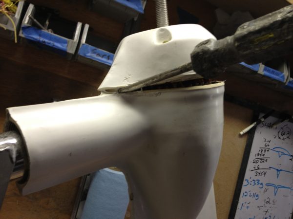
It is a little safer to pry in this area.
Plastic or rubber hammer striking here can sometimes separate the housing from the rotor and stator (assembly). Or use a pry bar (below);
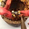
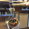
A pry bar will pull the rear bearing out of its seat, so that the rotor and stator can be removed as an assembly. You will be replacing the bearing anyway. A little spray lube directed at the rear bearing can help. Clamping the tail fin in a vise makes this a lot easier.
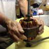
Separate the rotor and stator by holding them with the shaft (rotor) vertically and pushing the stator (the part with e copper coils) down. Have foam rubber or rags under the stator. It will release suddenly. Don’t have your fingers under the stator!
The easy way to remove the bearings is to take the shaft to a machine shop or alternator rebuild shop and have them press them off. It’s easy with a 3 ton press. Failing that, a hammer and a block of wood will work. CAUTION: THE MAGNETS ARE VERY STRONG AND WILL ATTRACT THE HAMMER HEAD. IF THE HAMMER HITS THE MAGNETS THEY WILL BREAK, SENDING SMALL PIECES FLYING. WEAR SAFETY GLASSES!
Use a short piece of 7/8 tube to install the new bearings. If you order the bearing from me, I supply it. Or, hit only the inner bearing race. Or have a machine shop do it. The bearing should be a tight fit on the shaft. If not, the shaft needs to be knurled or replaced. Leave the bearing in sunlight to make it easier to install. I use NTN 6203 LLB C3, contactless seal for low friction, high temp “electric motor” grease bearings.
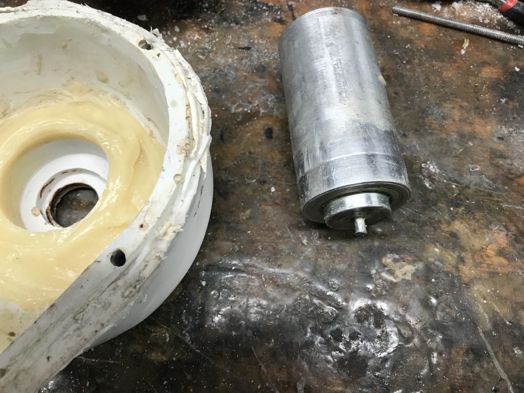
The rotor and stator will come out of the housing stuck together by the magnets. To separate them, hold the assembly with the shaft vertical, and push the stator off of the rotor. Caution: they will separate suddenly, and if your fingers are between the table and stator, weel; don’t hold it that way…
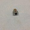
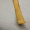
When Doug started building these, there was only polyester resin for the threads. Early on, he started embedding steel nuts about 1/4 inch down from the surface. This worked OK, but still there could be problems. I was using helicoils for a long time, but there still was issues whenever there was a void (air bubble) in the resin. The helicoil would be pulled out, and then the screw would not come out, requiring the stator be removed and the screw (and helicoil) cut off. I found that the best repair is to drill out the area to 3/8 inch and epoxy in an insert like this:
Typically, the hole and insert will then be exposed on the outer surface, and require grinding off and paint.
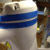
After I started building them, I put “divots” in the housing, made the screws longer, and added an external nut where the screw end was exposed in the divot.
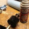
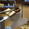
The magnets will probably have some rust on them. This is the paint I use. Check the cylinder that the magnets are mounted onto. It should be 1 5/8 from the closest edge of the front bearing. They sometimes come loose from the shaft. Check the assembly for straightness.
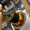
The thermal sensors are located on the back side of the stator. Heat them, slit with a razor, and peel off with needlenose. Solder all connections. Don’t drip solder into the stator coils.
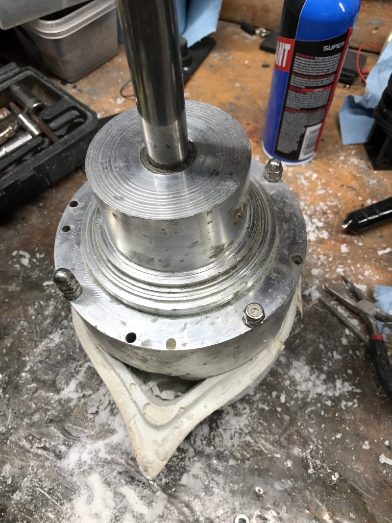
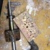
Occasionally the front cover bearing hole will not be centered. This is the tool I made to remachine the front cover. It uses a 2 inch end mill cutter on the end of the shaft,
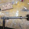
And then the hole for the seal needs to be centered (another custom built tool). Note the yellowish epoxy built up for machining purpose.
Reassembly Install the bearing seats. If yours are black, they need to be replaced with translucent or white seats. The black ones develop “set” and allow the bearing to go off center. The tapered part goes toward the stator. Grease the tapered part so the bearing will slip in easily.
Install the stator with one screw (to align the holes), with the thermal sensors down (inside the housing).
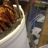
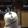
Slid the rotor into the stator. LOOK OUT: It will get sucked in very rapidly. Don’t have your fingers below the bearing (See photo)
The stator will probably come out of the housing by an inch or so. The magnets will pull it out, because the rear bearing is not in its seat. Use a plastic hammer or steel hammer with wood block to fully seat the rear bearing. When it is seated, the top of the metal of the stator will be close to even with the housing (as shown). Now you can remove that screw that is locating the stator.
Grease the front bearing seat, install the screws (but not all the way) and push and hammer the front cover into place.
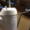
Mask the area on both side of where you will put your favorite sealant. Tinidad used bathtub caulking. I use 3M 4000. Before applying sealant, turn the shaft by hand. You can wrap string around the shaft and pull on it to measure the torque. New bearing will be 6-8 pounds. Touch each pair of wires together, and the shaft should get much harder to turn. This tells you it is working.
A few notes: If there is a lightweight spring in the housing (at the bottom of the hole where the pole goes in), grab it with vice grips and yank it out and throw it away.
The rotor will not turn in the stator until the front cover is fully installed. The magnets pull it to the side, and the front cover “locates” the front bearing.